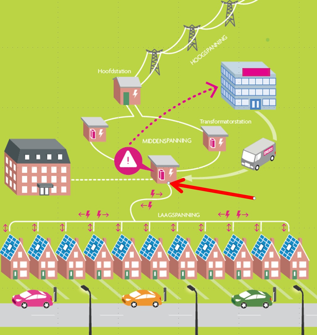
Location in the grid
The DigitalTF transmitter is placed in the MV/LV distribution station (red arrow). The transmitter electronics is a small DIN-rail mounted unit. In modern TN-S grids the coupler is placed in the LV Neutral line, directly after the coupling with Protective Earth (PE). The cost of a 630 KVA transmitter and toroid coupler is only a small fraction of a regular ripple control transmitter. The cost of a snap-on current transformer coupler is slightly higher. The current transformer coupler can be installed without powering down the MV station.
Transmitter timing/power
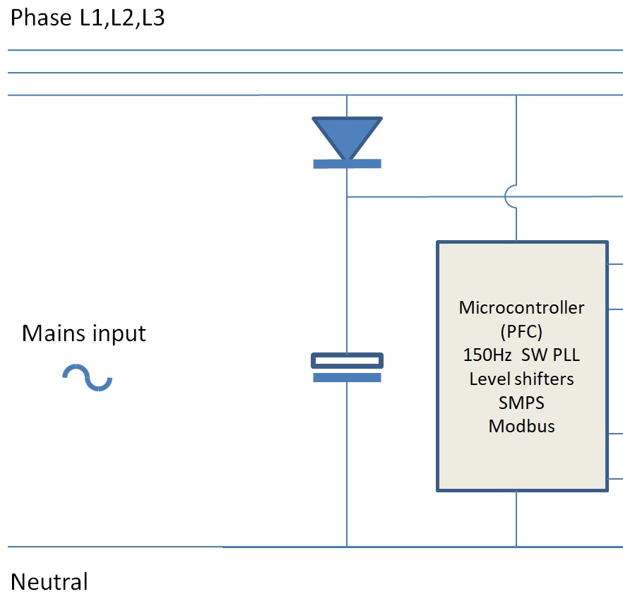
The transmitter is fed from one of the phases L1, L2 or L3, from which the 150/180 timing of the carrier is derived. The transmitter can be operated completely without internet by just monitoring power flows on the LV side of the MV transformer. Alternatively the transmitter is interfaced to the internet for remote control. For trials we have a prototype transmitter available that can be interfaced to relays via 4 dry contacts.
Carrier generator
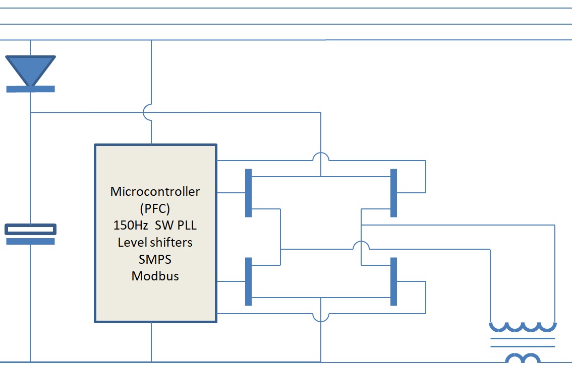
The 150/180 carrier is generated using a full bridge to feed the coupler transformer, employing MOSFET switches at relatively low power. Information is generated via Manchester coding.
DigitalTF transmits 24/7, such that these switches are operated continuously.
The carrier is coupled to the mains wiring by a toroid or snap-on current transformer of which the secondary winding is a single winding, the N.

A complete transmitter
In all, this is a complete DIN-rail mounted 640 KVA transmitter! As you can see, it does not make any sense to compare DigitalTF transmitters with conventional Ripple Control transmitters. In combination with a toroid coupler
which is about the size of a 300VA mains toroid transformer the cost of DigitalTF is at least one order of magnitude lower than conventional ripple control.
For installation without powering down the MV station we have a splittable coupler, much like a snap-on current transformer.